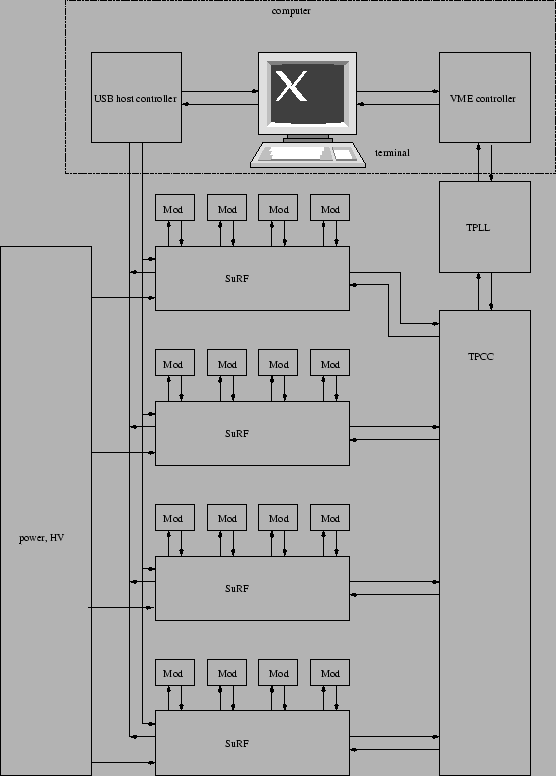
This section gives an overview over using the SURF board. We first describe how to connect the board to the rest of the burn-in setup. Then we walk the reader through some short diagnostic steps using host-side software that test whether the board works as expected.
![\fbox{\parbox[t]{0.99\textwidth}{{\bf Warning!} The state of the module
supply ...
...n the {{\sc SuRF}}\ board will be
corrected in future revisions of the board.}}](img4.png)
If you are the proud owner of a SURF board, you more likely than not also want to own AMBUSH (http://pixdata.lbl.gov/~surf/). At the AMBUSH prompt, you can perform some quick tests that your SURF boards are working.
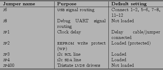
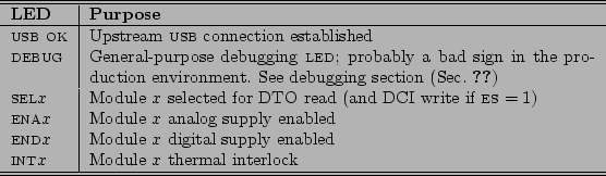
When you plug the USB end of the SURF board into the host computer, the USB OK LED must light up. If that is not the case, check that the J6 jumper is set correctly.
When the USB OK LED indicates that the board has upstream
connectivity, type surf_print_boards(); at the AMBUSH prompt
(remember to hit return twice). This should produce a listing like the
following:
Don't be shy about daisy-chaining all your boards together. In fact, attach a USB mouse or digital camera to the last one. As long as the USB OK LED lights up on each, the boards will be happy.002/022 4242/BEEF 200402LBL004 (rev 00.05.02)
002/020 4242/BEEF 200402LBL006 (rev 00.05.02)
Now you can address each module by its serial number. For example, if
board 200403LBL001 is connected to your computer, you can enable
the digital regulator for channel 2 on that board by saying
surf_brd_end("200403LBL001", 2, 1); and disable it with
surf_brd_end("200403LBL001", 2, 0); you can easily see if the
board understood you by checking that the END2 LED turns on when you
issue the former command and turns off when you issue the latter.
A comprehensive listing of functions that the SURF board understands is given in Ch. 4. That chapter also explains how you can invoke SURF board functions not by board name and channel number but instead by module serial number. Lastly, if you would like to see a not-so-quick list of tests, please consult Sec. 2.5; there we summarize the tests performed on newborn boards.
 |