All slow-control interaction between the user and the SURF board happens through the USB controller. Our USB controller chip (a Cypress EZ-USB AN2131) is a combination of USB line driver, RAM, souped-up 8051 microprocessor and i2c controller.
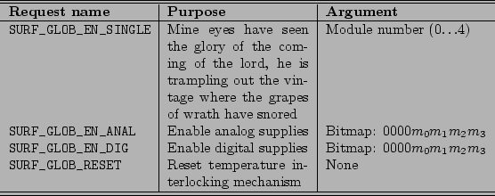
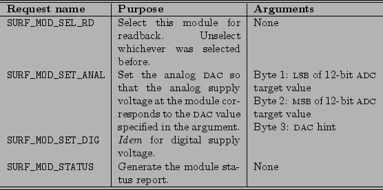
The USB controller part of the EZ-USB provides an interface to the SURF board for the machine running the AMBUSH software. It accepts requests to enable or disable the various features of the SURF board; set the settable settings; and read out the status of the board. Tables 3.1 and 3.2 list the requests that the host computer is allowed to make of the SURF board. (The additional requests required by the USB protocol specification are not listed in this here manual.)
Global requests are made through control transfers to the EZ-USB's endpoint EP0. The format of the request is shown in Table 3.3.
Module-specific requests are made through bulk transfers; for the ![]() th
module (zero-offset), the transfer is made to the
th
module (zero-offset), the transfer is made to the ![]() st endpoint.
(This arrangement is necessary because the USB specification
requires EP0 to be the control endpoint.) Byte 0 of a module-specific
transfer specifies the request (choose from one of those listed in
Table 3.2); the remaining 0 to 63 bytes are arguments to the
command as specified in Table 3.2. Note that if you ask an
endpoint for the status of its module by sending it the
st endpoint.
(This arrangement is necessary because the USB specification
requires EP0 to be the control endpoint.) Byte 0 of a module-specific
transfer specifies the request (choose from one of those listed in
Table 3.2); the remaining 0 to 63 bytes are arguments to the
command as specified in Table 3.2. Note that if you ask an
endpoint for the status of its module by sending it the
SURF_MOD_STATUS request, the next request you make to that
endpoint must be a bulk in request so that the endpoint can rid itself
of the status information it has generated. Table 3.4 shows
the format of the status report.
 |
 |
The microprocessor part of the EZ-USB has two eight-bit digital I/O ports and an i2c bus controller. The I/O bits are allocated as follows:
In addition to processing the set/get requests from the host computer, the 8051 also optionally corrects for the voltage drop in the module power supply. The firmware continuously digitizes the supply voltages sensed at the modules; it trims the regulator output until the sensed voltage falls within tolerance of the set voltage.
The controller firmware lives in the jboard/firm directory. To build it you need SDCC, the Small Device C Compiler, from http://sdcc.sourceforge.net. Typing make in the firmware directory will build two files: firm.ee and loader.ihx. The former is the actual firmware, in a format suitable for bootloading from the on-board EEPROM. The latter is loader firmware for the EZ-USB that allows the host computer to write to the EEPROM through the EZ-USB.
To download the firmware into the EEPROM on the SURF board, do the following: