


Next: Temperature interlock
Up: Hacking the hardware
Previous: Hacking the hardware
Contents
Linear regulators provide VDDD and VDDA for each module
connected to the SURF board. Fig. 3.1 shows the two regulators
supplying each module. The resistor R?/R? current-limits the regulators
to
The capacitor-diode network blah blah blah
makes the output voltage ramp when the regulator is enabled.
The EZ-USB processor on the SURF board (Sec. 3.6) can
set the voltage
level of each regulator by talking to the digital potentiometers (U?);
the processor can also disable each regulator entirely.
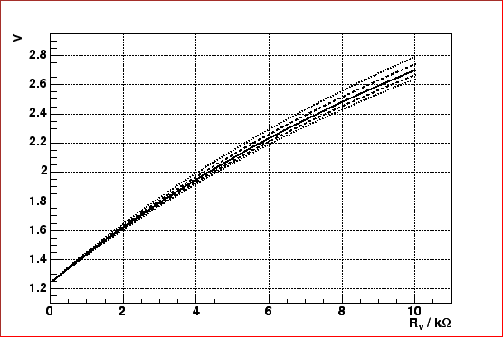
Fig. 3.4 shows a plot of analog and digital supply voltage as a
function of potentiometer resistance ( ).
).
Figure 3.1:
Regulator schematic
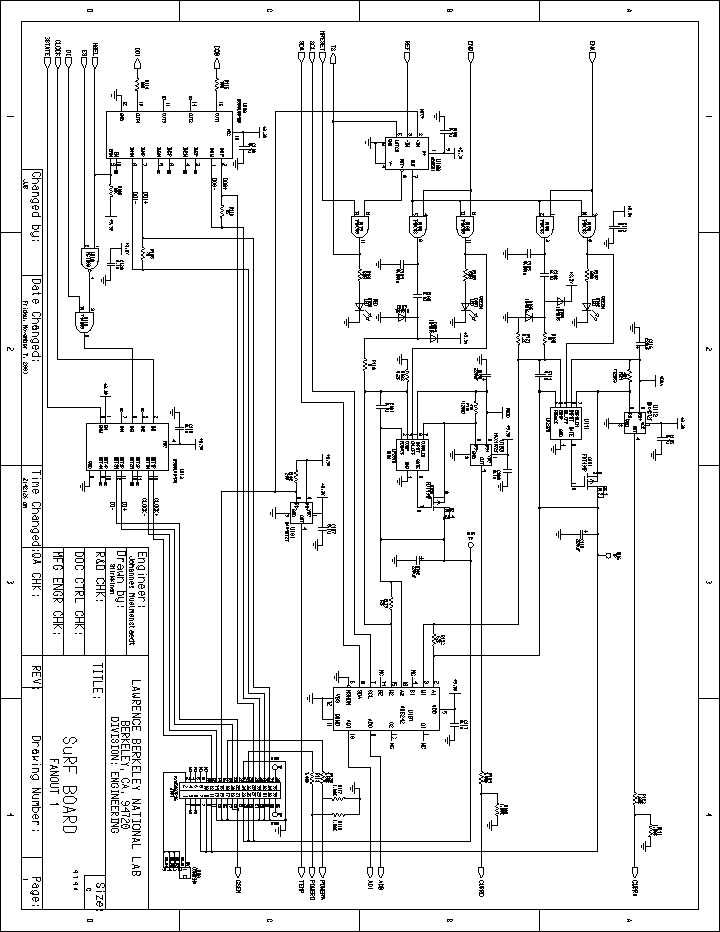 |
Figure 3.2:
LP2975 schematic[#!lp2975!#].
 k
k .
.
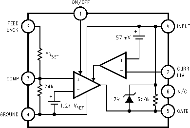 |
Figure 3.3:
LP2975 schematic[#!lp2975!#].
k.
|
Figure 3.4:
The dependence on
the high-tolerance (20%) internal 24-k resistor is shown. The
solid line indicates 0% deviation from 24 k, the dashed lines
 % and the dotted lines
  %.
%.
 |
Next: Temperature interlock
Up: Hacking the hardware
Previous: Hacking the hardware
Contents
Johannes Muelmenstaedt
2004-03-31